DESIGN FOR MANUFACTURING YIELDS BETTER PROFITS AND SHORTENS TIME TO MARKET
Parts intended for injection molding, simple or complex, can greatly benefit from optimizations found during the design for manufacturability (DfM) process. DfM is a collaboration between engineering and production to ensure a smooth project that delivers
superior-quality parts and a better return on investment. Whether you are designing parts in-house or contracting with a design firm, working with an experienced injection molding and tooling production partner early can help streamline the process.
Material Selection
When selecting a material for a plastic injection-molded part, consideration needs to be given to the end function and performance requirements, such as flexibility and rigidity, tensile strength, temperature and chemical resistance, regulatory compliance, final part appearance and more. Additionally, if the part requires special characteristics, your production partner will evaluate certain material characteristics such as melting point, cooling time and viscosity. Material selection and a part’s various wall thicknesses are also closely linked. For example, if a part has very thin wall sections or numerous areas that will be filled individually due to part geometry, the application may require a material with high-flow characteristics.
Wall Thickness
The part’s geometry may indicate a certain material. However, the inverse is also true. The material selection may affect how the part’s geometry needs to be designed.
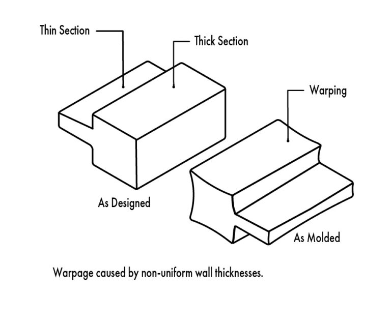
While each individual material has its own guidelines and recommended uses, there are several standard guidelines that apply across all plastic resins. One such guideline is to keep
primary wall thicknesses as uniform across a part as possible. This will help mitigate issues, such as warping.
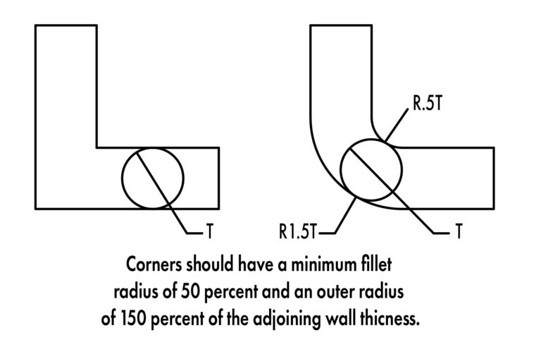
Corner Radii
Maintaining a consistent wall thickness throughout a part is
critical to ensuring a high-quality product. Nowhere is this truer than around corners and wall transitions.
Except in rare cases, it will be impossible with most materials
and geometries to produce a sharp corner with injection molding.
Therefore, a radius should be planned for in advance.
Wherever possible an external radius should be chosen that maintains the adjacent wall thicknesses. Leaving corner transitions too thick or too thin will result in issues previously described.
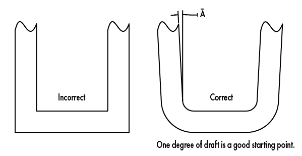
Draft Angles
One key difference between injection molding as compared to other manufacturing methods, such as CNC machining or 3D printing, is the need to physically eject the part off the mold once the molding cycle has been completed. To efficiently release
the part from the tool, it is imperative that it be drafted, or tapered. When designing a part for injection molding, this should be considered throughout the process. Certain materials and geometries may require specific levels of draft. Typically, a good place to start is one degree per side. Areas where more draft may be required are textured walls or features where telescoping
shutoffs are necessary. An improperly drafted feature or part can have cosmetic issues and may stick to the tool, causing the part and/or the tool itself to bend or break.
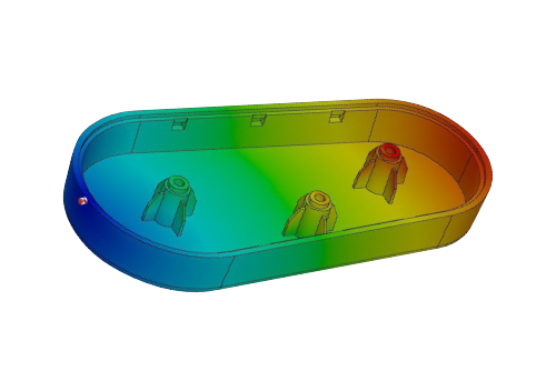
Mold-Flow Analysis
Mold-flow analysis software simulates the production
molding cycle of a part using a CAD file, an operator-chosen gate location and data of your selected material.
This simulation allows numerous parameters to be estimated and analyzed such as heating and cooling temperatures; how the part will fill; what pressures will be required to fill the part; and others. Running these simulations proactively addresses problem areas before they become an expensive and often time-consuming tooling change down the line. While these programs and simulations are immensely useful, they are technically complex and require subjectmatter experts to perform.